Innovative Turbines
Micro-Nozzle Technology
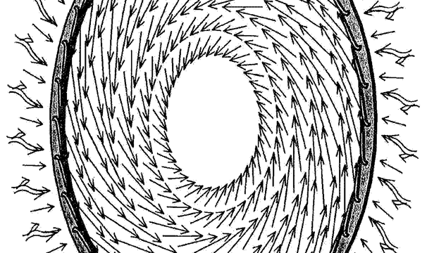
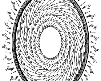
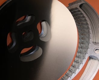
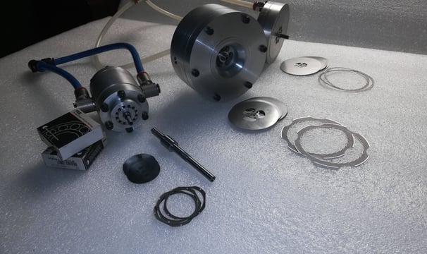
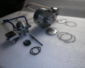
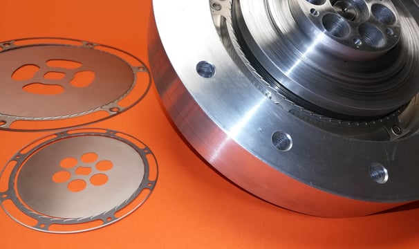
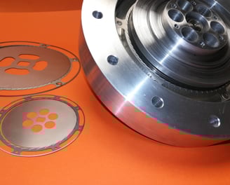
The fluid turbine we present consists of a stator with a high number of nozzles and a bladeless rotor with discs. The main characteristics of the pneumatic motor presented are excellent for applications requiring high processing speeds (easily reaching 100,000 RPM) with low power requirements (on the order of hundreds to a thousand watts). The paradigm to make this pneumatic motor is the overlapping of many laminates, both in the stator and rotor, obtained through chemical etching. This production process allows the creation of parts with precision not achievable with other methods, and they come at nearly negligible cost compared to the complexity of the passages. With this construction process, the cost of the main parts of the motor decreases significantly as the precision of the pieces increases. The etching mask is made using a photographic process directly on the metal sheet; details can be as small as a hundredth of a millimeter. The cost of the motor decreases significantly, and it can be said that the most expensive part of the assembly is the high-speed bearings

Our projects
Pneumatic motor
Compared to conventional bladed turbines, this type of pneumatic motor is insensitive to impurities in the inlet air (the maximum acceptable size of particles dragged is comparable to the stator passage clearances) and has good efficiency even in versions with a smaller rotor diameter. Due to the limitations in construction and precision for small machines, which significantly affects machine efficiency, the bladed turbine rotor has lower efficiency and, therefore, suboptimal fluid consumption. This does not happen with a bladeless rotor, as the work exchange occurs due to fluid viscosity, low velocity gradients, and the rotor "accompanies" the fluid inside it along a spiral path. The fluid's smooth flow without abrupt changes in direction is the reason the machine can tolerate motor fluids with pollutants and condensate inside. Pollutants cannot wear out the rotor because the differences in rotor-fluid velocity are low, and there are no sudden changes in direction, preventing significant impacts on the rotor from particles and practically nullifying rotor wear. By appropriately adjusting the rotor disc diameter and quantity, you can freely control the speed-torque plane. A reduction in rotor diameter corresponds to an increase in speed and a decrease in torque, if necessary; this reduction can be compensated by increasing the number of rotor discs. The axial size increase caused by adding more discs is not significant, as rotor discs can be very thin. For example, 100 rotor discs with a diameter of 3.5 cm can occupy approximately 4 cm (including air passage) and produce a power of about 300 W at a rotation speed of 100,000 RPM. The same number of discs but with a double diameter provides roughly the same power at a rotation speed of 50,000 RPM but with doubled torque. This comparison shows that this type of machine easily achieves the required rotation speed and torque by selecting the rotor disc diameter and quantity appropriately.
Steam Turbine
Our turbines are divided into two characteristic rotor diameters: 64 mm and 120mm. For each of these diameters, it’s possible to obtain different powers using a different number of rotor disks. The power depends on the type of fluids, the inlet pressure (here for all the data, the inlet pressure is the pressure before the stator nozzles) and from the number of disks. The power starts from 9W for every disk of 64 mm of diameter using air at the relative pressure of 1.1 bar and ambient temperature, to the maximum of around 30W for each disk in the case of a 120mm rotor diameter and superheated steam at the temperature of 320°C. These data are obtained by theoretical three-dimensional CFD models. Regarding the fluid mass flows, these start from 24W for each g/s with air at ambient temperature and 1barg to a maximum of 94W each g/s for superheated steam at the same pressure and a temperature of 320°C. It’s important to remark that these are theoretical power results from a three-dimensional CFD model; in reality, these need to be reduced by a factor that is inversely proportional to the power of the machine. That is because the model is simplified: here are not modeled extremity effects, bearings, ventilation effects etc. So, to obtain the real power of the machine, it is necessary to consider a power that is 20-30% less than the theoretical. For the selection of the rotor diameter, it is good to consider a number of rotor disks greater than 10, so it is not recommended to use a 120 mm diameter for machines with less than 500w, due to the great influence of extremity effects. It’s important to remark that in the case of steam (or, in general, vapor of substances), a grade of superheat is necessary: if there is condensation, the efficiency and the power of the machine will decrease to nearly zero due to the reduction of the nozzle speed caused by condensation. Example: Required power of the turbine is 100W, I have compressed air at ambient temperature and 1.5 bar gauge. The required theoretical power will be 120-130W, so the best diameter to use is 64mm, so the number of disks will be around 15-20 (130/9) and the machine will process around 6 g/s of compressed air (130/24).

The Tesla turbine's efficiency has revolutionized our energy recovery processes in ways we never imagined.
John Doe

Incredible technology! The micro-nozzle system significantly improved our energy output and reduced waste dramatically.
Jane Smith
